|
|
|
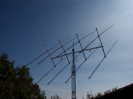
I have been entering the EME community with a 4* 39el array but as soon as i realized it was only alimited entry point the antenna was upgraded to 8 * 39 (13 lambda).
The antenna got destroyed in a snow storm after only 8 months of activity :
|
|
|
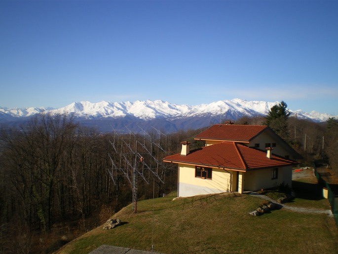
I was forced to more than 1 year of QRT during which i moved to a different QTH while planning the new antenna system.
I have been considering the 13 lambda antenna as not convenient for a big array especially from the mechanical point of view in strong wind conditions.
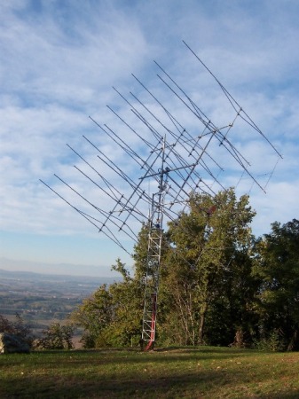
I have therefore selected shorter antennas based on the project of DJ9BV (26el 8.5 lambda) being very well proven and considered, the result is a 4 by 4 antenna array put into a usable state during October/2007.
|
|
|
|
|
The Antennas are phased with
open wire
feed lines (8mm aluminium tubing ),on each group of 4 the impedence is transformed back to the original 200 ohms and then paralleled to 100 at the 4 + 4 joint and finally transformed to the final 50ohms at the feeding point (thanks to the suggestion of Jan DL9KR).
Here a diagram of the feeding system.
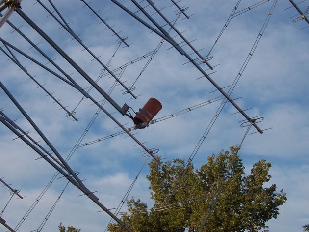
The feed point is waterproofed with heavy industrial plastic tubing and houses the antenna relay, the LNA (0.4db) , the 1 to 1 balun (silvered brass), and unfortunately also a UHF cavity in front of the LNA to eliminate the interference of a nearby FM broadcast transmitter:
|
|
|
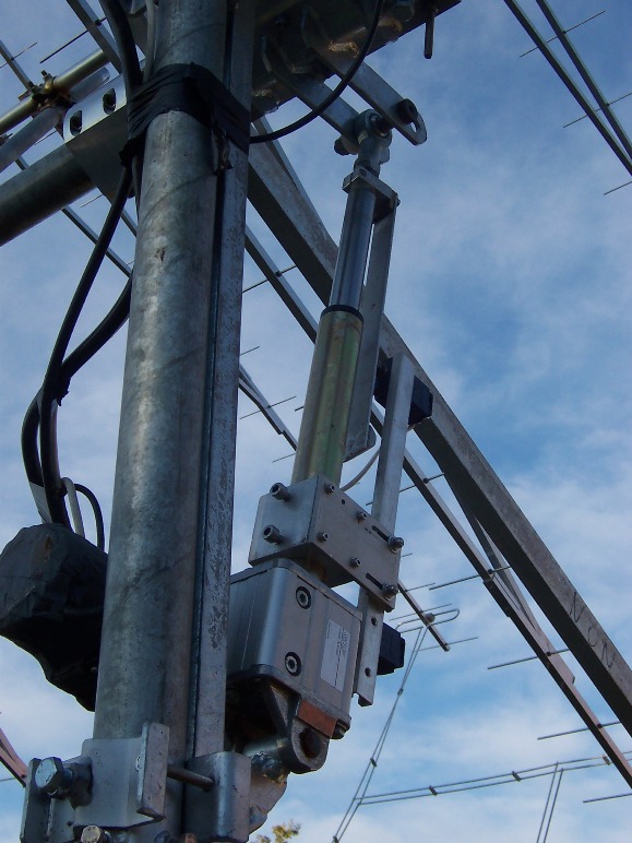
A surplus linear actuator is used to elevate the array.
The DC motor applied to the actuator has it's own worm gear in addition to that of the actuator.
The motion reduction is such to make the full 90 degrees elevation in more than 5 minutes time:
|
|
Unfortunately i could not have a horizontal scale in degrees. The result is somehow different from what expected from antenna emulation, actually the second lobe is stronger than third and very little difference between the first two. The attenuation from the main to the first and second seems to be acceptable ( > 18 dbs). The diagram with the low signal level points is somehow distorted by the pick up of background noise.
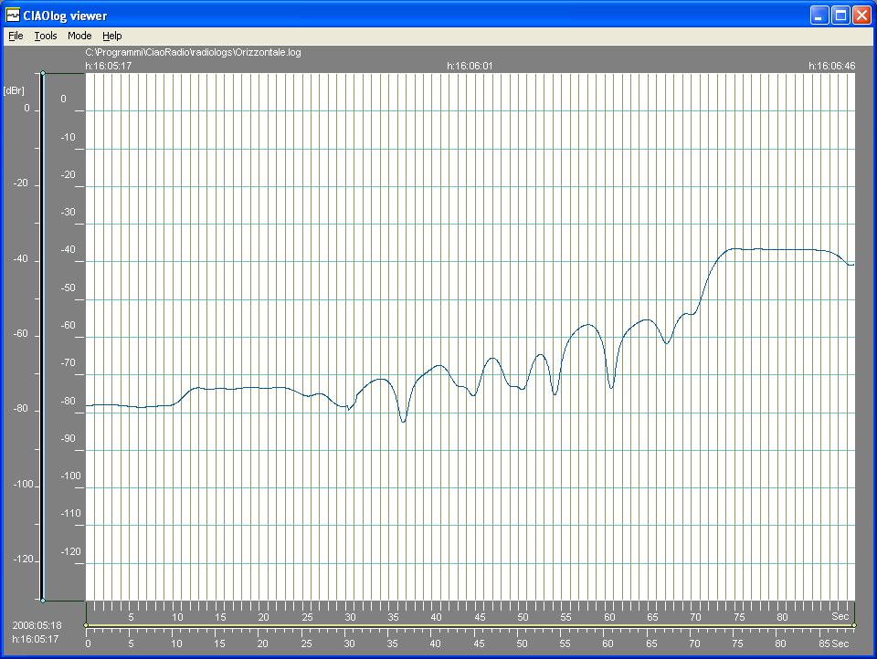
Also here I did not have any mean for synchronising the horizontal scale with antenna position.
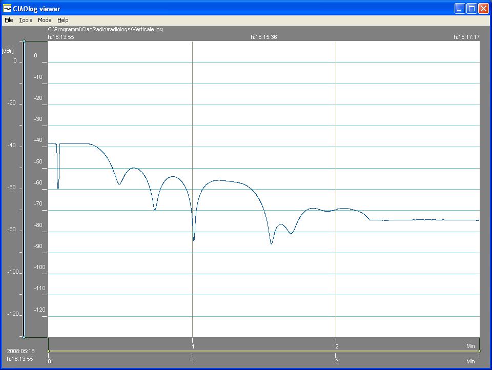
On the vertical plane the first secondary lobe is larger than second but still second is larger than third.
I
expected a better attenuation from main lobe to first secondary (< 12 dbs on
diagram) .
Sun noise reading at best was 41dbs which was simply the effect of an exceptionally strong solar flare, normal readings are usually consistent with VK3UM calculator prediction.
In my frontend i loose a fraction of db in a cavity ahead of the LNA, tough i am not living in an urban area (may be for the elevation) the surroundings are very noisy and it's difficult to find a direction with a low noise level .
The following diagram shows a sun noise reading ina quiet sun condition by moving the azimuth antenna position:

The VK3UM was foreseeing a
16.5db sun noise for my system.
The echoes are all most always very consistent with
at best about 25db above noise and even an SSB signal returned by the moon seems
to be intelligible.
The output power from my amplifier during the test is slightly over 1kw, the feed line is made of 20m of 7/8 coax plus 3m of Ecoflex15.
The total transmission loss is about 1db.